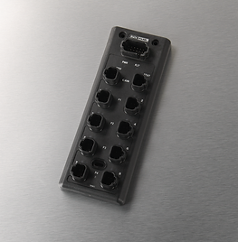
Considering it's the height of summer at the time this article is released, let's talk about heat for a second. Your machine is built to withstand heat, whether from the environment or machine-generated, but how well does it survive heat day in and day out? Is it possible for a single electrical control component to prevent the deterioration of hydraulic performance in high heat? This is where the xtremeDB comes in; among its many features, one of its most significant is that it can counter the effects of heat in your hydraulic control system. Since the launch of the product in 2016, three variants perfect hydraulic control of not just bang-bang valves, but also the more complex proportional valves.
A Recap
A hydraulic proportional valve (electro hydraulic) uses a variable electrical signal, usually called “demand signal”, to change the hydraulic flow or pressure output from a valve. This is typically done by varying the voltage across a wound coil, which in turn moves an internal spool or poppet. The higher the voltage, the more power is available to move the spool or poppet. In mobile applications, the most common control is to use a pulse width modulated (PWM) demand signal to directly control the coil. In industrial applications, it is common for more expensive proportional valves to have this PWM driver built into the valve, which is controlled by a 0-10 volt, or 4-20 mA signal from a PLC. Mobile controllers tend to have PWM drivers, which allows for the lower valve cost option to be used.
So What??
In a wound coil, as the temperature increases (from internal and external influences), the resistance decreases significantly. Consider an application with a hydraulic-driven conveyor with a constant load over a workday. In the morning on start-up (say 40 °F), the conveyor is set at 60% speed or 100 FPM; by 3 PM, however, air temperature is 80 °F, hydraulic oil temp is 120 °F, and the coil has been operating all day, creating its own heat. The coil resistance, and consequently the valve output, can change significantly. A 20% change is not unheard of, but it's enough that the conveyor has sped up to 120 FPM. That means the operator has to continuously compensate or live with a changing process variable… or use a closed loop current control on the valve coil like what can be found in xtremeDB PWM(i) outputs.
Meet xtremeDB...
By monitoring the outgoing current against the return current to a coil, the effects of resistance change can be automatically eliminated. PWM(i) has always been a feature in our DP-34044-1 family of combo input/output blocks, as well as in the DP-34044-4 all-output blocks. Those same PWM(i) outputs are now available on the DP-34044-3 blocks at no extra charge.
The difference between the “-3” and “-4” is that on the -4, the two outputs in the ports are “paired.” This means that in a single port, the “A” and “B” signals cannot be on at the same time. This reduces the number of control messages, thus reducing busload, which works well for exclusive functions (e.g. Plow Up/Plow Down), but it's not a good fit for all applications. The -3 does not have that limitation. Both these units also feature two 10 Amp digital ports for driving bigger loads such as work lights.
To learn more about these modules, visit our page on the xtremeDB Family. Order yours today.


